
Type 1 surge protective devices sit at the origin of an installation and handle the partial lightning current that reaches a building with an external lightning protection system, while Type 2 devices protect distribution boards and downstream equipment from switching and induced transients. Many installations now use combined Type 1+2 units to simplify coordination. BS 7671 Section 534 sets out where each type belongs.
TL;DR:
- With an external lightning protection system, install Type 1 at the origin; otherwise, Type 2 is standard at the origin for homes and small businesses.
- Sensitive electronics may need downstream Type 2 or Type 3 devices; each Up rating must remain below the protected equipment’s withstand voltage.
- Use manufacturer coordination data when pairing devices, because the upstream SPD should have a higher Up rating than the downstream unit.
- Protect incoming telephone, data, and coaxial lines as well as the mains supply, or surges can bypass the electrical SPD through those routes.
- A red or failed status indicator means the SPD provides no protection; inspect it after major surges and during routine electrical maintenance.
Table of Contents
- Technical differences: waveforms, protection level and energy ratings
- How to place SPDs correctly under BS 7671 Section 534
- Choosing and coordinating SPDs that actually work together
- Protecting data and telecom lines alongside the mains supply
- How Type 1 and Type 2 SPDs fail and what to look for
- Keeping SPDs effective through maintenance and testing
- Weighing the cost of Type 1 against Type 2 protection
- Why SPD class affects how much protection you actually get
- Matching surge events to the right SPD type
- Installer notes: common mistakes we see in the field
- Testing and compliance services to validate SPD installations
- FAQ
- Sources
Technical differences: waveforms, protection level and energy ratings
The distinction between the two types comes down to what they are built to survive and how well they clamp the voltage that reaches your equipment. Type 1 devices are tested against a simulated partial lightning current waveform representing the energy profile of a direct or nearby lightning strike reaching the installation through bonding conductors. Type 2 devices are tested against a faster waveform, which models the lower-energy transients produced by switching operations, nearby faults or induced surges travelling along the supply network.
That difference in test waveform translates directly into construction and energy-handling capacity. Type 1 devices need a higher energy-withstand rating, expressed as Iimp, because they must survive the partial lightning current without failing catastrophically. Type 2 devices are rated for lower energy but can still achieve a low protection level, known as Up, which matters because a lower Up means less residual voltage reaches the equipment downstream.
Up is the figure specifiers watch most closely. A high-energy Type 1 device with a relatively high Up will stop the installation burning down, but it will not necessarily protect sensitive electronics on its own. That is why layered protection exists.
- Type 1 sits at the origin where an external lightning protection system is fitted, handling partial lightning current with a high Iimp rating.
- Type 2 sits at the origin or at distribution boards where there is no external LPS, or downstream of a Type 1 device, prioritising a low Up.
- Combined Type 1+2 units handle both roles in a single enclosure, which is increasingly common in domestic and light commercial consumer units.
A warehouse with a lightning conductor network on its roof needs a Type 1 device at the incoming supply. A typical house without an external LPS is usually adequately served by a Type 2 device at the consumer unit, as IET Wiring Matters sets out.
How to place SPDs correctly under BS 7671 Section 534
Placement is not a matter of preference. BS 7671 ties the type of device to the presence or absence of an external lightning protection system and to where sensitive loads sit in the installation.
- Check for an external LPS. Where one exists, Section 534 requires a Type 1 SPD fitted as close as possible to the origin of the installation.
- Default to Type 2 at the origin where there is no LPS. This is the standard requirement for most domestic and small commercial supplies.
- Add Type 2 or Type 3 devices downstream wherever sensitive equipment, IT racks or medical devices need a lower residual voltage than the origin device alone can deliver.
- Consider a combined Type 1+2 unit where space in the consumer unit or distribution board is limited and separate coordination calculations are impractical; this is a recognised and increasingly preferred route.
- Check earthing and bonding conductor sizes against the SPD manufacturer’s instructions, since an undersized earth path undermines the device’s ability to divert surge current safely.
- Review separation distances between the SPD and the protected equipment, because excessive cable length between the two can reintroduce induced voltage that the device was meant to remove.
- Confirm incoming services are included in the design, not just the mains supply, since lightning and switching transients can enter through data or telecom lines just as easily.
Clause 443.4.1 governs when protection against transient overvoltages is required at all, covering risks to life, loss of public services, damage to irreplaceable items or disruption to commercial activity. Section 534 then governs how the devices are selected and positioned once that requirement is established.
Choosing and coordinating SPDs that actually work together
Specifying a single SPD in isolation is rarely enough. The devices that end up protecting an installation properly are chosen as a coordinated set, with each one’s characteristics checked against its neighbours.
- Confirm each device meets BS EN 61643 (or the equivalent IEC 61643 series), since this is the standard that defines Up, Iimp and the test classifications referred to as Type 1, 2 and 3.
- Check the Up rating of every device in the chain and make sure it falls below the withstand voltage of the equipment it protects.
- Check the Iimp or In rating against the expected exposure: higher for origin devices with an external LPS, lower for downstream units protecting electronics.
- Confirm the enclosure and IP rating suit the installation location, particularly for external meter boxes or exposed distribution boards.
- Use manufacturer coordination tables where available rather than assuming compatibility between different brands, since coordination between an upstream and downstream device depends on matched let-through characteristics.
- Prefer a combined Type 1+2 unit when the distance between origin and distribution board is short enough that separate coordination calculations add complexity without real benefit.
The coordination rule that matters most is simple to state and easy to get wrong in practice: the upstream device should have a higher Up than the downstream device, so the downstream unit takes over clamping duty before the upstream one is forced to operate. Mixing SPDs from different manufacturers without checked coordination data risks a scenario where neither device operates as intended.
Pro Tip: Ask the manufacturer for published coordination or “energy coordination” data between the specific upstream and downstream models before installation, not after a fault has already occurred.
Once fitted, verify the installation with insulation resistance and continuity tests appropriate to the SPD manufacturer’s instructions, and record the results on the installation certificate.
Protecting data and telecom lines alongside the mains supply
A mains SPD protects the mains. It does nothing for a transient that enters through a telephone line, a data cable or a cable TV feed, and that is a genuine gap if those services are ignored.
- Fit line SPD modules on incoming telecom, data or coaxial services where equipment connected to them is sensitive or expensive to replace.
- Bond cable shields and earthing systems together so that all protective earths reference the same point, avoiding voltage differences between separately earthed systems.
- Use isolators or surge-rated connectors on long external data runs, such as those feeding outbuildings or external cameras.
IET technical guidance warns that protecting only the electrical installation while leaving other incoming services unprotected creates an alternative route for transients to bypass the mains SPD altogether. This is where Lightning Protection Zone thinking helps: an LPZ design treats the building as a series of zones with decreasing surge risk towards the centre, and every service entering a zone, mains or otherwise, needs protection matched to that zone’s exposure.
How Type 1 and Type 2 SPDs fail and what to look for
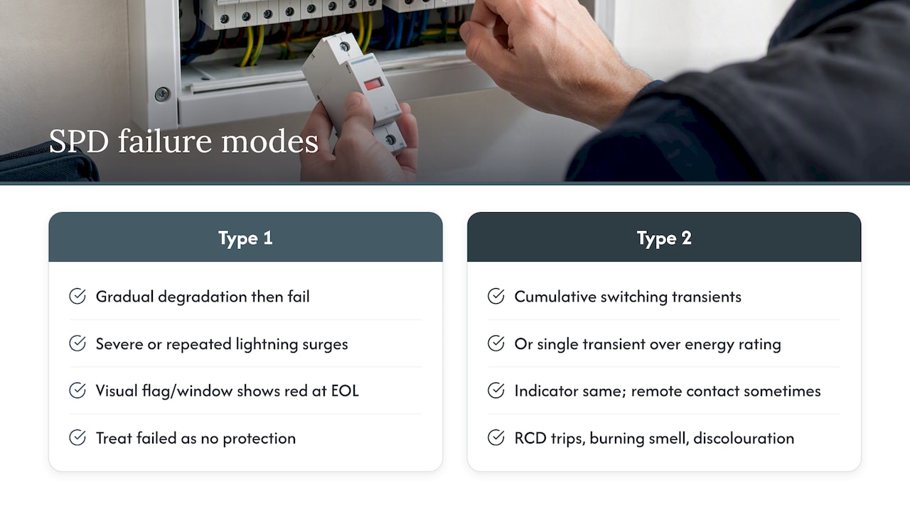
Type 1 and Type 2 devices tend to fail in different ways because they are built for different stresses. A Type 1 device subjected to repeated or unusually severe lightning-related surges can degrade gradually, with its metal oxide varistor components losing clamping efficiency before they fail completely. A Type 2 device more commonly fails after a cumulative number of smaller switching transients, or suddenly after one transient that exceeds its energy rating.
Most SPDs carry a visual status indicator, usually a coloured window or flag that changes from green to red when the device has reached end of life. Some combined units include a remote contact that can trigger an alarm or a building management system signal, which is useful where the consumer unit is not inspected often.
A device showing a failed indicator should be treated as providing no protection at all, not reduced protection. Surge protection does not fail safely into a “weaker but working” state. It either diverts the current within its rated parameters or it does not, so a failed indicator means the circuit it serves is currently unprotected until the device is replaced.
Nuisance tripping of an associated RCD, a burning smell near the consumer unit, or visible discolouration on the SPD housing are all signs worth investigating immediately rather than at the next scheduled visit.
Keeping SPDs effective through maintenance and testing
An SPD that was correctly specified and installed does not stay effective indefinitely without attention. Visual inspection of the status indicator should happen at a frequency suited to the building’s exposure, and many specifiers tie this to routine electrical maintenance visits rather than treating it as a separate task.
A periodic inspection under an EICR should include a check of the SPD’s condition, its connections and the continuity of its earth path, since a loose or corroded connection undermines the device’s ability to divert surge current even if the SPD itself is otherwise healthy. BS 7671 guidance treats SPD condition as part of the wider installation assessment rather than a standalone check.
After any significant electrical event, such as a nearby lightning strike or a reported power surge, the SPD’s indicator should be checked before assuming the installation is still fully protected. Replacement is straightforward in most consumer units because SPDs are typically designed as plug-in modules, but the replacement must match the original specification or better, not simply the nearest unit on the shelf.
Weighing the cost of Type 1 against Type 2 protection
Type 1 devices cost more than Type 2 devices of similar build quality, largely because of the higher energy-withstand components and more robust construction needed to survive partial lightning current. That upfront difference matters most where a Type 1 device is genuinely required, such as a building with an external lightning protection system, rather than being a decision taken on preference.
For most domestic and small commercial installations without an external LPS, Type 2 protection at the origin is both the regulatory default and the more economical choice, since it meets the requirement without paying for energy-withstand capacity the installation does not need. Combined Type 1+2 units sit between the two in price but often work out cheaper overall than installing two separate devices and paying for the coordination assessment between them.
The real economic argument for surge protection generally is replacement cost avoidance rather than the price of the device itself. A single Type 2 unit at a consumer unit costs a small fraction of what it takes to replace a boiler control board, a consumer electronics setup or networking equipment damaged by an unprotected surge.
Why SPD class affects how much protection you actually get
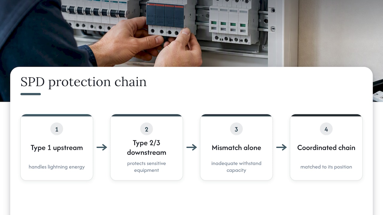
The type classification of an SPD is not a marketing label, it is a direct statement of what the device has been tested to survive and how well it limits voltage while doing so. Fitting a Type 2 device where a Type 1 is required under Section 534 leaves the installation without adequate withstand capacity for the energy a lightning-related event can deliver through bonding conductors, regardless of how good that Type 2 device’s Up rating looks on paper.
The reverse mismatch matters too. A Type 1 device alone, even a well-specified one, often has a higher residual Up than sensitive electronic equipment can tolerate, which is precisely why downstream Type 2 or Type 3 devices exist in a properly coordinated design. The effectiveness of the whole installation’s surge protection depends on every device in the chain being matched to its position, not on any single device being the best available on its own.
Matching surge events to the right SPD type
Different surge events suit different devices, and recognising which is which helps explain why a single SPD rarely covers every scenario on its own.
Direct or nearby lightning strikes, and the partial lightning current that travels through bonding conductors when a building has an external lightning protection system, are squarely a Type 1 problem. These events carry far more energy than switching transients and need a device built to survive that energy without failing. Utility-side switching operations, such as a transformer tap change or a large motor starting on a shared feeder, produce the faster, lower-energy transients that Type 2 devices are built to clamp. Internal switching within a building, including large motors, lift systems or heavy plant starting and stopping, generates similar transients that a well-placed Type 2 device at the distribution board handles effectively. Induced surges from nearby lightning activity that do not strike the building directly tend to sit between the two profiles, which is one reason combined Type 1+2 units have become a practical default in many consumer units.
Installer notes: common mistakes we see in the field
The most frequent error is mixing SPDs from different manufacturers without checking coordination data, leaving a mismatch between upstream and downstream Up ratings that neither device was designed to cover alone. Undersized bonding conductors are a close second: an SPD can only divert current as fast as its earth path allows. The third recurring gap is ignoring secondary routes, particularly telecom and data lines, which leaves a surge an easy path around an otherwise well-specified mains installation.
Verification matters as much as specification. An EICR that includes a proper check of SPD condition, connections and earthing continuity catches problems a visual glance at a green indicator light will miss.
— Gemma
Testing and compliance services to validate SPD installations
A correctly specified SPD only does its job if the installation around it is sound, and that is where our testing services fit in. 
Our EICR and fixed wire testing checks earthing continuity, connections and SPD condition as part of a full electrical installation condition report, giving you documented evidence that your surge protection is wired and earthed the way the manufacturer intended. We also carry out PAT testing to confirm that the equipment behind your SPDs is operating safely, which matters once protection is in place and you want proof the whole chain holds up. Book an inspection and get a clear, documented picture of where your installation stands.
FAQ
What is a Type 3 SPD and where does it fit?
A Type 3 SPD is a low-energy device fitted close to sensitive equipment, typically within a few metres of the load it protects. It is used as the final stage in a coordinated cascade, following Type 1 or Type 2 devices upstream, as described in BS 7671 Section 534.
What should never be plugged into a surge protector?
High-draw appliances such as space heaters, tumble dryers or power tools should not rely on a plug-in surge suppressor, since these devices are rated for continuous current far below what such appliances demand. Medical life-support equipment should also avoid relying solely on a general-purpose surge suppressor without specialist advice.
Should the SPD be installed before or after the main breaker?
In most consumer unit designs, the SPD is connected after the main switch but ahead of the final circuits, so it sees the incoming supply while still being isolated when the main switch is off. The exact arrangement depends on the manufacturer’s installation instructions and the board layout.
What do current regulations say about surge protection devices?
BS 7671 (18th Edition, Amendment 2) requires protection against transient overvoltages under Clause 443.4.1 where risks to life, public services, heritage assets or commercial activity exist, with Section 534 governing device selection and placement. Where an external lightning protection system is present, a Type 1 SPD is required at the origin; otherwise a Type 2 device at the origin is the standard requirement.
Can CityPat test whether my SPD installation meets regulations?
Our EICR and fixed wire testing service assesses earthing, bonding and connection integrity as part of a full installation condition report, which covers the conditions an SPD needs to function correctly. We do not design or specify SPD systems, but our reports give you documented evidence to support compliance discussions with your installer or insurer.